You open the laminator, anticipating a perfect module. But as you inspect the panel, you see it: the subtle, frustrating misalignment of a solar cell or busbar. It’s a small shift, but one that’s enough to impact performance, compromise quality, and ultimately, hurt your yield. If this sounds familiar, you’re not alone—and the cause might not be what you think.
For years, the industry has focused on „peel strength“—how well the layers of a solar module stick together. While important, this only tells half the story. The real culprit behind costly component shifting is often an invisible force that acts horizontally: inter-laminate shear strength. It’s the force that resists the layers sliding against each other during the dynamic, high-pressure environment of the lamination cycle.
Understanding this hidden force is the key to moving from frustrating production losses to predictable, high-quality output.
The Usual Suspect vs. The Real Culprit: Peel Strength vs. Shear Strength
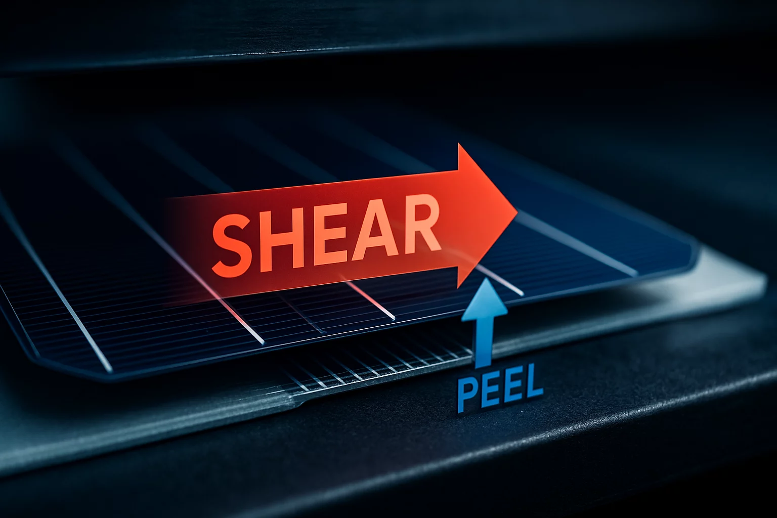
Imagine trying to separate two pieces of wood glued together. Pulling them directly apart tests the peel strength (or adhesion). It measures the vertical force needed to delaminate the layers. This is what most traditional quality tests measure.
Now, imagine trying to slide those same two pieces of wood against each other. The resistance you feel is the shear strength. It’s the horizontal force needed to make one layer slip across the other.
During lamination, immense heat and pressure cause the encapsulant to melt and flow. This creates powerful shear forces that push and pull on every component inside the module. If the shear strength between the layers is too low at this critical moment, cells and ribbons can—and will—move. This is especially true for today’s larger M10 and G12 cells and complex multi-busbar (MBB) designs, where even tiny movements can lead to significant yield loss.
Traditional peel strength tests completely miss this dynamic, leaving manufacturers guessing why their components keep shifting.
The „Slippery Stage“: A Critical Window in Your Lamination Cycle
The most vulnerable moment in a module’s life happens in the first few minutes inside the laminator. As the encapsulant (like POE or EPE) heats up, it enters a „gel phase“ before it fully cures. Our research at PVTestLab shows that some modern, fast-curing encapsulants have surprisingly low initial shear strength during this phase.
We call this the „slippery stage.“
For a few critical minutes, the encapsulant acts more like a lubricant than a glue. In this window, the pressure and flow dynamics inside the laminator can easily push cells and ribbons out of alignment. By the time the encapsulant cures and develops its final, high bond strength, the damage is already done.
This explains why a module can pass final adhesion tests with flying colors yet still exhibit significant internal shifting. The final bond is strong, but the stability during the process wasn’t there when it mattered most.
From Guesswork to Data: How to Predict Shifting Before It Happens
How do you fight a problem you can’t see? By measuring it. Instead of relying on guesswork, we can quantify an encapsulant’s shear strength and map its behavior throughout the lamination cycle.
By conducting systematic shear tests, we can generate a shear strength vs. time/temperature curve. This graph provides a clear „fingerprint“ of how a material behaves under real process conditions, revealing the exact duration and depth of the „slippery stage.“
At PVTestLab, our methodology involves creating test laminates (e.g., glass-encapsulant-backsheet) and using a specialized setup to measure the precise force required to shear the layers apart at different points in the curing cycle. This approach provides hard data, not just theory.
Our data reveals a clear threshold: we have successfully linked low shear values—specifically less than 5 N/cm²—during the first 5-8 minutes of the cycle to observable cell and ribbon displacement in full-size M10 modules. This kind of quantitative insight is essential for effective material testing and validation and forms the foundation for a robust manufacturing process.
Locking It Down: Practical Solutions to Prevent Component Shifting
Once you can measure the problem, you can solve it. The data from shear strength testing points to two primary pathways for eliminating component shifting: process optimization and material selection.
1. Process Optimization
Sometimes, the material is right but the process needs a tune-up. Rather than using a standard, one-size-fits-all heating and pressure recipe, a more intelligent approach can make all the difference.
We’ve validated that process adjustments can „close the window“ on the slippery stage. Solutions include:
- Extending the pre-heating phase: This allows the encapsulant to build some initial shear strength before full pressure is applied.
- Introducing a multi-step pressure profile: Applying pressure gradually gives the material time to stabilize, locking components in place before the encapsulant fully flows.
Fine-tuning the solar module lamination process with this data-driven approach can often resolve shifting issues without changing any materials.
2. Strategic Material Selection
In other cases, the data may show that an encapsulant’s inherent properties are simply not a good fit for a specific module design or production speed. Encapsulants can have vastly different rheological profiles—how they flow and harden. A material that works perfectly for a small, standard module might be too „slippery“ for a larger, bifacial design.
By comparing the shear strength curves of different encapsulants, you can choose a material with higher „green strength“ (its strength during the early, uncured phase) that provides the stability needed for your specific application. This is a critical step when prototyping new solar modules to avoid costly issues when scaling to mass production.
Frequently Asked Questions (FAQ)
What’s the difference between shear strength and peel strength in simple terms?
Think of it this way: peel strength is about resisting being pulled apart (like a sticker), while shear strength is about resisting sliding sideways (like brakes on a car). Both are crucial for module quality, but it’s shear strength that keeps components from moving during the lamination process.
Why is this problem more common with newer, larger solar cells?
Larger cells (like M10 and G12) have more surface area, which means the shear forces acting on them during lamination are greater. Furthermore, complex multi-busbar (MBB) interconnection designs create more potential points of movement. A process that was stable for smaller cells may not be robust enough for these modern designs.
Can I just extend my lamination time to fix this?
Not necessarily. Simply making the cycle longer without understanding the material’s behavior can be inefficient and may not solve the root cause. The „slippery stage“ is about the initial phase of curing. A targeted adjustment, like a multi-step pressure profile, is often far more effective than just adding minutes to the overall cycle time.
What is an encapsulant’s „green strength“?
„Green strength“ is a term for the mechanical strength of a material (like an encapsulant) before it is fully cured. In this context, it refers to the initial shear strength that develops as the material begins to cross-link. High green strength is desirable for preventing component shifting.
Your Next Step in Mastering Lamination
Moving beyond peel strength to focus on inter-laminate shear strength marks a fundamental shift from a reactive to a proactive approach to quality control. It allows you to replace guesswork with data, predict problems before they happen, and build a lamination process that is stable, repeatable, and ready for the next generation of solar technology.
By understanding the hidden forces at play inside your laminator, you can ensure every module you produce meets the highest standards of quality and performance.